
Berlin, September 3rd, 2026
How Do You Test Six Inverters Simultaneously?
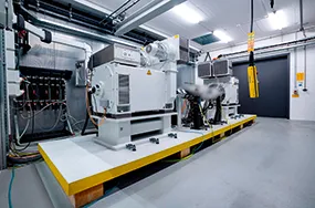
When modern electric drive systems are developed, it is no longer sufficient to test individual components in isolation. Inverters and control units must prove themselves under realistic conditions, respond to simulated vehicle states, and simultaneously provide measurement, diagnostic, and calibration data. For this purpose, ATESTEO operates specialized test benches for the development and validation of modern powertrains. The company is one of Germany’s leading providers in the field of drivetrain testing.
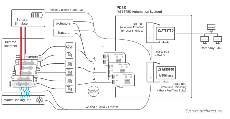
At the heart of the system is PDES, the automation system developed by ATESTEO. The software executes test programs, integrates measurement and actuator hardware, and communicates with the devices under test. One specific application illustrates the resulting requirements: six inverters are tested simultaneously in an environmental chamber. Each inverter is connected to the automation system via CAN FD. In addition, XCP on CAN FD is used to exchange measurement, diagnostic, and calibration data with the control units.
However, that is only part of the task. The battery simulator, water-cooling system, conditioning units, sensors, and actuators must also be integrated reliably into the test program. Depending on the task, this is done via CAN, EtherCAT, or analog and digital interfaces. During testing, the inverters expect cyclic CAN FD messages, respond to the simulated system environment, and simultaneously return their measurement and diagnostic data.
A vehicle environment built in software
Modern test benches for electric drive systems do more than reproduce individual signals. They must provide the devices under test with an environment that replicates, as closely as possible, the behavior of the complete system in which they will later operate. The inverters therefore receive not only individual control commands, but also a continuous stream of the messages they would expect from other control units and components in the vehicle.
This so-called restbus simulation emulates the nodes of the communication network that are not physically present. The automation system generates the required CAN FD messages, changes operating states, and responds to replies from the devices under test. This allows different driving scenarios, load conditions, and fault cases to be incorporated reproducibly into the test program without requiring a complete vehicle.
At the same time, XCP on CAN FD is used to read internal measurements from the control units and exchange diagnostic and calibration data. The CAN interface therefore performs several tasks at once: it provides the simulated communication environment, transmits control commands, and enables access to the data required to evaluate the test run.
Additional test bench components also have to be integrated. A battery simulator creates the electrical conditions required for each test. The water-cooling system and additional conditioning units maintain defined thermal conditions, while sensors and actuators provide further measurements and input variables. All these systems must be coordinated within a common test sequence.
The challenge lies not only in the number of connected devices. What matters most is the precisely timed interaction between all participants. Messages must be sent at specified times, measurement values must be processed promptly, and responses from the devices under test must be captured within the intended cycles. Only then can test conditions and results remain reproducible.
The timing requirements are correspondingly demanding. CAN-based real-time communication must maintain typical cycle rates of 100 hertz and, in many applications, even 1 kilohertz. This corresponds to processing cycles of ten milliseconds and one millisecond, respectively. User interactions, visualization, network access, or other Windows processes must not delay these operations.
Real time despite Windows
ATESTEO therefore divides the PDES system between two computers. The PDES SIU serves as the Windows front end for operation, visualization, and configuration. This is where test sequences are prepared, parameters are configured, and the information recorded during the test is displayed.
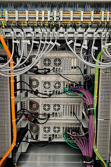
The PDES RTU, by contrast, forms the isolated real-time unit. It executes the test programs and handles the time-critical communication and control tasks. The two systems communicate via a peer-to-peer network. The SIU can be connected to the corporate network, while the RTU operates as an isolated, dedicated machine.
This division of responsibilities prevents user interactions, remote access, or unwanted Windows processes from affecting the timing of a test. While the SIU handles configuration and visualization, the RTU can focus entirely on the deterministic execution of the test program.
ATESTEO uses Kithara RealTime Suite on the RTU. It enables time-critical routines to run in real time on Windows, supports data exchange via EtherCAT, and performs CAN FD communication directly from the real-time environment. This allows the automation system to remain on a Windows-based PC platform without relying on the operating system’s standard scheduler for critical processes.
CAN FD messages can therefore be integrated directly into the test bench’s real-time processing. The communication cycles run together with the test program and the other inputs and outputs. State changes, measurement values, and responses from the devices under test can thus be processed within the defined time windows.
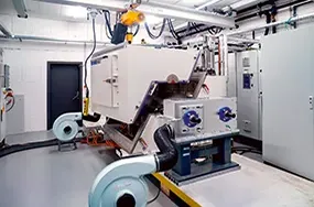
EtherCAT is also part of this architecture. The real-time network can be used to connect additional measurement and actuator components, while CAN FD is used primarily for communication with the inverters and their control units. Analog and digital interfaces supplement the system wherever devices or signals are not connected via a fieldbus.
The different communication paths remain part of a common automated test sequence. This is particularly important when a change at one point must trigger an immediate response elsewhere. A change in the state of the battery simulator, for example, may require new CAN messages while measurements are being recorded and cooling or actuator components are being controlled at the same time.
Many buses in a compact space
Four-channel PCAN-PCI Express FD cards from PEAK are used to connect the inverters. In typical test benches, ATESTEO uses up to four of these cards, providing up to 16 CAN nodes. The configuration described here uses three groups with four CAN FD nodes each.
The multichannel design makes it possible to integrate several separate CAN networks within a single compact real-time unit. Each inverter can be addressed through its own bus connection, while all communication is processed centrally within the PDES RTU. These connections carry the cyclic CAN FD messages used for restbus and environment simulation, as well as the data transmitted via XCP.
The hardware supports both CAN FD and Classical CAN. This allows existing and new generations of control units to be operated within the same automation architecture. CAN FD can transmit up to 64 bytes of payload in a single frame. This provides additional capacity for applications in which more extensive measurement or diagnostic data must be exchanged alongside the cyclic control information.
Another important aspect is the galvanic isolation between the PC and CAN sides. Test benches containing inverters and other power electronics are electrically demanding environments. The isolation therefore improves communication robustness and protects the PC-side interface against unwanted electrical interference originating from the test setup.
For Kithara, direct low-level access to the CAN interface hardware is particularly important. Communication can only be integrated fully into the Kithara real-time environment if the card can be accessed reliably at a low level. The PEAK cards therefore provide the physical connection to the devices under test, while Kithara RealTime Suite enables deterministic processing within the automation system.
ATESTEO has relied on Kithara’s real-time system and PEAK’s CAN solutions for many years. Horst Frantzen, Head of Software Products at ATESTEO, describes the interaction between the two technologies as follows: “Kithara’s real-time extension forms the foundation of our automation system. Its hard real-time capabilities provide the basis for an open architecture in which even complex test sequences can be implemented reliably. It is complemented perfectly by PEAK’s CAN solutions, which we have trusted for decades and which have proven themselves in our test bench systems through their reliability, consistent performance, and straightforward integration. With Kithara as a dependable technology partner and PEAK’s latest CAN XL solutions, we are ideally equipped to meet the requirements of future communication standards in the test bench environment.”
The next step: CAN XL
The current application demonstrates what can already be implemented in practice with CAN FD: multiple inverters communicate with the automation system in parallel, test programs are executed deterministically, and measurement, diagnostic, and calibration data are exchanged via XCP. At the same time, the battery simulator, cooling system, sensors, actuators, and other test bench components are integrated into the sequence.
However, the requirements of future generations of control units continue to increase. Higher data rates, larger payloads, and more powerful communication structures will become particularly important as increasing volumes of measurement values, status information, and control data have to be transmitted simultaneously.
ATESTEO, PEAK, and Kithara are therefore already working on the integration of CAN XL. ATESTEO intends to integrate the new standard into PDES so that future generations of control units can be tested under realistic test bench conditions. Kithara is extending its real-time system to support new CAN standards such as CAN XL and CAN FD Light. PEAK is providing the hardware platform, low-level documentation, and interface technology required for this purpose.
Marcel Haß, Technical Director at Kithara, describes the development as follows: “CAN XL is the logical next step in automotive real-time communication for us. We are therefore integrating the standard into Kithara RealTime Suite at an early stage and, together with PEAK and ATESTEO, creating the technological foundation for future generations of test benches and control units.”
The collaboration between the three companies combines different areas of expertise into a complete system. ATESTEO contributes its experience in the development and automation of powertrain test benches. PEAK provides the CAN interfaces used to connect the devices under test. Kithara ensures that the time-critical communication and control processes can be executed deterministically on Windows.
This makes it possible to test six inverters simultaneously, simulate realistic operating conditions, and process the required data within defined timing cycles. At the same time, the underlying architecture remains open to additional test bench components and future generations of automotive communication.
Image credits: Photos © ATESTEO/Kithara, Graphic © PEAK by HMS Networks